QM true positioning
Bonus tolerances for GD&T
A true balancing act
By Richard Clark
A bonus tolerance is arguably one of the most difficult
concepts (in Geometric Dimensioning and Tolerancing) to
explain to the powers that be. For almost all other
characteristics called out on a drawing, here is our
specification… this is our minimum, this is our maximum, and
anything outside of these parameters is non-conforming
product (scrap or rework).
When True Position (positional location) is called out on
a drawing, the tolerance is applied at LMC (least material
condition), MMC (maximum material condition), or RFS
(regardless of feature size). If LMC or MMC is listed, we
can calculate a wider tolerance, or bonus, depending on the
actual size of the measured feature.
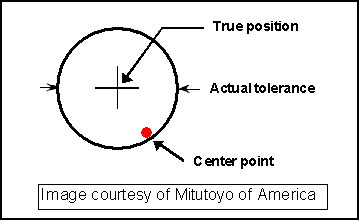
We should start with understanding RFS because it allows
no bonus to our location tolerance zone. If a drawing calls
for positional location and does not specify LMC or MMC, the
center of the measured feature must lie within the tolerance
zone specified, regardless of the feature size.
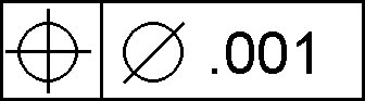
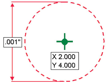
This on the drawing...
...means this on the part.
The concept of a bonus tolerance is simple. Diameter is a
tolerance of size. However, the location also affects the
fit and function of the feature to its mating part(s). Bonus
tolerances allow the tolerance amount not used in the
diameter to be applied to the location. This allows the
maximum use of tolerances while keeping the fit and function
intact.
Imagine we're trying to assemble a 5" long plug into a 4"
deep bore. If the diameter of the bore was 2.0000" and the
diameter of the plug was 1.9999", the plug would have to be
straight within (or probably below) 0.0001" to ensure it
would fit and function. On the contrary, if our plug
diameter was 1.9995" it could have a straightness deviation
of almost 0.0005" and still fit. This is a form example as
opposed to location but the concept is very similar.
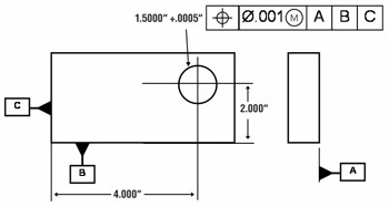
In our example, we'll use an inside feature. Our drawing
states we have a diameter tolerance of 1.5000" +0.0005" (so
our MMC would be 1.5000"). In addition, we have a positional
location tolerance of 0.001" applied at MMC.
The intent of positional location when applied at LMC or
MMC is to ensure an acceptable amount of clearance between
the part you're making and its mating part. If the size of
our inside feature is at MMC (smallest diameter) we need to
be within 0.001" location for the mating part to fit (our
part) properly. Let's look at a graphic illustration (not to
scale) of our part at MMC (smallest diameter) and largest
diameter.
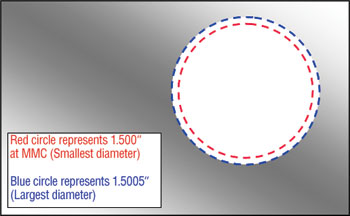
The larger we make our inside diameter, the more “room”
we have for the location to be outside of the 0.001"
location tolerance zone, but the clearance remains
acceptable. Whatever amount above MMC (above our minimum)
our diameter becomes is applied as a bonus to the tolerance
of the positional location. If the diameter of our feature
was 1.5005", the 5 tenths we are above MMC would be applied
to the location tolerance which then becomes 0.0015".
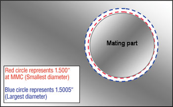
If we look at the graphic illustration with the mating
part added, you can see why the bonus tolerance is applied
to our location. If we are at MMC (smallest diameter), we
have no “room” to spare with our location. If we are at the
largest diameter, we have room to spare so a bonus tolerance
is applied.
It's a textbook example of the Axiom of Equality
(addition) found in a Jr. High level Algebra book. If we
look at the diameter tolerance and the location tolerance as
two sides of a balanced equation, whatever we add to one
side we also add to the other side to keep the two sides in
balance:
1.5000" (diameter at MMC) = 0.001" (location)
But if we were to add:
1.5000" + 0.0003" (diameter) = 0.001" + 0.0003" (location)
1.5003" (diameter) = 0.0013" (location)
And that's all there is to it. Trust me, if it were any
more difficult than this, yours truly couldn't teach it. So
let's always try and break it down to counting beads on a
string… shall we?
Author's note: This article is a follow up to
“Exposing the Myth of True Position” which ran in the
October 2003 issue of Tooling and Production Magazine.
Richard Clark is a CMM Programmer and Trainer who is
affiliated with CMM Technology Inc.
(San Clemente, CA). To receive a copy of “Exposing the Myth
of True Position” and/or a FREEWARE copy of his Bonus
Tolerance calculator for Excel, e-mail feedback to
rcmetrology@yahoo.com.
editor's blogs

Off the Toolpath
EASTEC marks 30th show with spotlight on medical devices
The recession hasn’t stopped business, if the activity at the EASTEC Advanced Productivity Exposition is to judge. The show, in its 30th year, drew 570 exhibitors, down from 608 in 2008 and 650 in 2007. About 15,000 attendees pre-registered. Last year’s show tallied 14,000 attendees. The largest industrial tool trade show on the East Coast, EASTEC was held May19-21 in West Springfield, MA.
by Dennis Seeds, Editor-in-Chief
digital edition
On target
For a new generation of parts, automated centerless grinding fills the bill
The taper test
Prototype fixture finds the reason why vexing toolholder wear marks appear
Watchful eye keeps tabs on 575 machine tools
Aerospace supplier sees new productivity heights, lower costs
From 12 hrs to 25 mins
Giant steps for faster cavity hogging, square-offs follow re-tooling