December 2007 Edition
automation
Successful robotic deburring is really a matter of choices
By Aaron Odham, application engineer, ATI Industrial Automation
 Robotic deburring and surface –finishing applications continue to grow in number as lean manufacturing techniques demand more from less. Automated surface finishing is a process that can be widely used in the manufacturing technology industry for a variety of applications ranging from aerospace to automotive to ship industry.1 Coupled with increased health–care costs associated with maintaining dangerous manual deburring systems, these robotic deburring systems have a huge monetary savings potential if executed correctly.
One key to a successful robotic deburring system is the ability of the system to adapt to ever–changing part tolerances and burr sizes. Utilizing active or passive force control tools such as those from ATI Industrial Automation in the system will greatly increase a robotic deburring application's chance for success.
In the most generic sense, successful deburring or surface finishing requires a consistent end result regardless of the starting conditions. For deburring and deflashing, success will require: a) completely removing the unwanted burr/parting line, b) leaving the surface free of chatter and scallops, c) not removing too much parent material. Of the three requirements, leaving the surface free of chatter and scallops is the most difficult for human operators. Completely removing the burr/parting line and not removing too much parent material are the most difficult for robots. Humans are wired for change and very easily adapt to changing conditions, but are not very consistent. Robots, conversely, are wired for consistency, but cannot easily adapt to changing conditions unless given "prompts" to change based on feedback from an ATI Six–Axis Force Torque Sensor or using adaptive (compliant) tooling such as ATI's Versafinish or Flexdeburr.
Active force control tools provide prompts to the robot to actively (in real time) change its program trajectory as defined by a controlled–correction routine. These changes can adjust the path speed and adjust the cutting forces. These types of systems are typically more expensive than passive devices, but offer more accuracy and repeatability.
Passive force control tools adapt to the changing part or unwanted burr independent of the robot, but are not as precise or accurate.
Let's examine the pros and cons of both systems, as well as provide general areas of concerns for robotic deburring.
Deburring, finishing art
Much like a master jeweler refines his technique over years of experience to cleave a perfect diamond and produce a brilliant, radiant gem, so must a master finisher rely on experience to remove the right amount of material and produce a beautiful "gem." Applying too much force and in the wrong direction to a diamond results in a useless shattered diamond. Applying too much force in the wrong direction to a part yields useless scrap material – or worse, rework.
To achieve a perfectly deburred or finished part, an operator must constantly adjust the amount of force, location and direction of force, and the speed at which this force is applied to a workpiece as that workpiece constantly changes. The learning curve for this type of work is very steep and filled with costly mistakes. Unfortunately, once the operator has mastered this art, he may be burned out and no longer wish to continue this dirty, dangerous, and degrading job and so the cycle continues with the next new operator.
During the learning process, an operator uses his senses to continually adjust (in real time) his process to achieve an acceptable result. Whether he remembers and applies the same techniques he used Friday afternoon the following Monday morning is a different story. Although we are the most dynamic machines on earth and can adjust to an ever–changing environment, we are not repeatable and lack the physical stamina to achieve the consistent end results demanded in most deburring or surface–finishing applications today.
And now the science
Deburring, grinding, and surface finishing are basically quite simple. For a given material (assuming the material composition and characteristic doesn't change during the process) and given media (assuming the abrasiveness doesn't change), the end result is dependent only upon the media's surface speed, the contact pressure of the media (contact force divided by contact area), and the rate at which the media is presented to the workpiece (feedrate). Most of these "feed and speed" variables are readily available from media manufacturers. Once these variables are determined, the end results will be consistent. This seems all too simple, but the laws of physics and machining do not change for deburring or surface finishing, as many process engineers might lead you to believe.
Humans are wired for change and very easily adapt to changing conditions, but are not very consistent. Robots, conversely, are wired for consistency, but cannot easily adapt to changing conditions unless given 'prompts' to change based on feedback from an ATI Six–Axis Force Torque Sensor or use adaptive (compliant) tooling such as ATI's VersaFinish or Flexdeburr.
If this process is so simple, then why do so many robotic deburring and surface finishing applications fail? The answer is simple: The parts are not consistent to begin with and the unwanted burrs are not consistent. Because robots cannot learn over time, once they are programmed, they consistently repeat their programmed moves day after day; hence, they cannot adapt to the changing parts or unwanted burr size. The best the operator can hope for is "nominal" results with a rigid robot and rigid tooling.
Meshing art and science
Compliance is the ability of a tool to maintain contact and cutting force with the workpiece. Controlling this force reduces the deburring and surface–finishing variables to only "feed and speed," which are well–documented values readily available from media and carbide suppliers. Compliance also decreases the physical taught points along a curvilinear surface that the robot must follow because the robot will adjust its own path or the compliant tool will extend or retract to follow the part. These systems greatly reduce gouging the cutter into a part and help prevent the cutter from coming off the part (deburring air).
Compliance can be achieved through a variety of techniques that include both active and passive force control systems. Active systems require a data link back to the robot controller to provide information and therefore are closed–loop systems. They might use accelerometers, Six–Axis Force Torque Sensors, or even the robot's own servo–torque outputs to help control the cutting force. These systems are the most repeatable, accurate, and flexible of all of force control systems, but typically carry a higher price tag. Active systems are best suited to applications that have very demanding surface requirements where one can justify the expense.
Passive systems do not have a data link back to the controller and are open–loop systems where the robot and tool operate independently of one another. These systems might include springs, mass counterweights, electrical actuators, or pneumatic devices such as the VersaFinish and Flexdeburr tools to maintain the controlled–contact force. These systems are not as repeatable or accurate as their "intelligent" cousins, but what they lack in brains they make up for in value. Passive systems are much less expensive and great for brute–force deburring, where the end result is defined only by a burr-free surface with loose tolerances.
Active force control
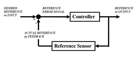 Active force control systems continually measure the output (cutting force) of the system and compare the feedback (actual cutting force measured by a Six-Axis Force Torque Sensor) to the desired reference. Case in point: The desired reference is the cutting force that must be maintained to achieve a desired finish. This value is predetermined and obtained through trial-and-error testing. Once the desired cutting force is known and entered into the controller, the actual cutting force is subtracted from it and an error signal is generated. The error signal is then fed into the controller, which adjusts the output until it matches the desired input driving the error signal to zero.
Error signal management
Depending on the complexity of the reference sensor – single-axis load cell to multi-axis – force/torque sensor with accelerometers, the actual reference might be as simple as a scalar value or as complex as several vectors that define the resultant cutting force and direction in three dimensions. Choosing the right type of reference sensor is dependent upon the application and expertise of the integrator. From a best-case control scenario, more information is always better.
Once an error signal is generated, the controller can drive it to zero through a variety of ways, but we will only examine two possibilities. The first technique, feed control, varies the feedrate to maintain the desired cutting force, while the second technique, pressure control, adjusts the robot's trajectory to maintain the desired cutting force. Each of these techniques has their specific advantage, disadvantages, and limitations.
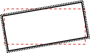
Feed control
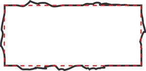 A. Consistent location and part size Inconsistent burr or flash size OK for feed control
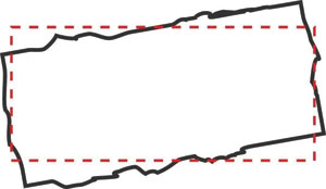 B. Inconsistent location or part size Inconsistent burr or flash size Not OK for feed control
Feed-controlled robotic-deburring or surface-finishing applications utilize active force control to adjust the feedrate at which the robot presents a part to some abrasive media or cutter. The force in the path direction is constant. The feed is variable and the path is constant2. This system is exceptional for removing irregular amounts of material, such as flash and parting lines from parts that are relatively consistent. The disadvantage to this system is that the parts must also be repeatable and their locations relative to robot path must be repeatable. Because the robot is adjusting only the feedrate, it cannot distinguish between unwanted material (flash or parting line) and a part that is out of position or is inconsistent. Damage to the parent material will result if the part's location and size is not tightly controlled.
To use this type of control architecture, the robot is programmed to follow a part that has already been processed and is a "known good." The resultant trajectory will not change and all successive parts will have material removed to the robot's defined programmed trajectory. As the unwanted material grows, the feedrate will decrease to remove the excess material.
The addition of a vision system to properly identify the location of parts and adjust the trajectory prior to deburring makes the feed-control system an extremely accurate and repeatable system capable of tackling the most versatile of all deburring or surface- finishing applications.
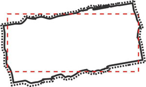
Pressure control
 A. Inconsistent location and part size Consistent burr or flash size OK for pressure control
 B. Inconsistent location or part size Inconsistent burr or flash size Not OK for pressure control
Pressure-controlled robotic-deburring or surface-finishing applications utilize active force control to adjust the trajectory of the robot to maintain the desired contact pressure following the part profile (cutting force / cutting area). Force in the controlled direction and speed along the surface is constant3. This system is ideal for compensating for inconsistent part locations and varying part sizes with consistent burrs. The disadvantage of this system is that it cannot compensate for large variances in burr or flash size. If the unwanted material varies greatly, there is the potential for some of it to be left on the part. Because the robot is only adjusting the trajectory to maintain a desired cutting force, it cannot distinguish between a part that is out of position or is inconsistent and unwanted material (flash or parting line). Failure to remove all of the unwanted burr or flash is possible if the burr size is not closely maintained. This might require a pre-process to bring the unwanted material to a more controlled dimension.
To use this type of control architecture, the robot is programmed to follow a part that has already been processed and is a "known good." This trajectory is the base path that the robot will follow while maintaining a constant contact force. As the robot moves around the part the reference sensor constantly measures the contact-force components. The idea is to add a component toward the object when the force reading is lower than the desired contact force, or add a component that points away from the object when the force reading is higher4. When the measured force vector is less than desired, the robot will move towards the object, and when the measured force vector is greater than desired, it will move away. The "new" resultant trajectory will change and follow the profile of the parts as their size and locations change.
Passive force control
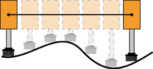 Two taught points with axial or linear compliance
Passive force control systems do not measure any cutting forces, but simply adapt to the part and apply a constant force. These systems are similar to the pressure control systems discussed earlier, but instead of the robot adjusting the trajectory to follow the part, the cutting head of a passive device moves, or complies, to follow the part independent of the robot. These systems are also susceptible to the same issues as the pressure control system, as discussed previously. Because their cutting force is constant, they are best suited for applications that have relatively consistent burrs or flash, but have poor part-to-part tolerances or poor location repeatability. These systems might include springs, mass counterweights, electric actuators, or pneumatic devices such as the VersaFinish and Flexdeburr to maintain the controlled-contact force.
Passive force control tools also decrease the number of physical taught points along a curvilinear surface, which the robot must follow, because the tool will extend or retract to follow the part. These systems greatly reduce gouging of the part by the cutter and help prevent the cutter from coming off the part (deburring air).
Spring-controlled systems are very simple to integrate. The contact force varies proportionally with deflection according to the spring's force constant, and can provide less than desirable results, proving very difficult to program.
Mass counterbalance systems are also simple to integrate, but limit themselves to applications where the counterbalance's mass always acts with gravity to oppose the cutting forces. These systems are also limited because the cutting force is difficult to change and inertial effects typically limit them to floor-mounted systems.
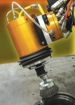
Pneumatic actuation is by far the most common means of providing compliance in commercial surface finishing systems5. Pneumatic force control systems are more difficult to integrate, but offer advantages that outweigh these difficulties. In its simplest form, a piston controls the cutting force, which is constant and proportional to the supplied pressure times the piston area. These systems are typically not affected by inertial loading and can be floor-mounted or robot-mounted. These systems are easy to control and can use programmable pressure regulators to vary the cutting force. The discussion from this point forward will relate only to pneumatic passive force control devices.
Passive compliant tools
Consider the different types of passive compliant systems. As these tools deflect to control the cutting forces, they must do so in a controlled and predictable way or severe chatter and part damage will occur.
The types of compliance consist of linear compliance (deflection along a straight line such as the VersaFinish), radial compliance (deflection along a radius such as the Flexdeburr), rotational compliance (deflection along an arc), or a combination of radial and linear compliance. No matter what type of compliant tool is used, the cutting force (controlled force) must be directed along the line of compliance. These tools should also have stiffness in the path direction to help prevent the tool from being pulled ahead by the shear forces created during the cutting process or lagging behind as the tool moves along the part. Special care must also be taken during programming to accommodate for cutter deflections. Points of contact between the part and media should also be minimized to ensure the cutting force remains along the direction of compliance. This often means rotating the tool to ensure the cutting force is acting in the correct direction. Conversely, the more directions of compliance a tool has (degrees of freedom), the easier it is to program, but it becomes more difficult to control.
Linear compliance
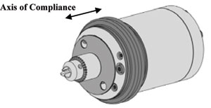 Linear compliance, often called axial compliance, in the Versafinish allows the spindle to deflect along one axis of compliance with a constant contact force through the entire stroke of the pneumatic device controlling it. These tools are excellent choices when using cone (90-degrees) cutters or cup brushes, because they offer great stiffness perpendicular to the control force. The stiffness will help minimize the chance for the reactive shear-cutting force to pull the tool and cause unwanted chatter.
Special care should also be taken when using linear compliant tools for plunging into a workpiece for drilling or countersinking operations because the reactive shear forces can be high and very unpredictable. This can cause the compliance system to bind because of increased side loads.
Radial compliance
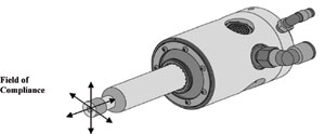 Radial compliance in the Flexdeburr allows movement from a center position through 360° along a radius of compliance with a constant contact force. When the contact force is removed, the rotating shaft of the tool will return to the center of the compliant field. These tools are ideal for radial brushes and help control the side loads on the radial brush. Because the cutting action is radial, they are great for removing parting lines and flash from cast parts.
Radial compliant tools do not have increased stiffness in the path direction. Special care must be taken not to apply too much contact force, which might cause the cutter to pull off center due to the increased reactive shear cutting forces. Radial compliant tools also perform poorly with more than one point of contact on the brush or cutter. This creates a force imbalance and will cause the media to chatter violently as it bounces between the two points of contact.
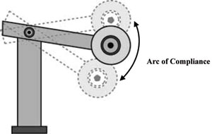
Rotational compliance
Rotational compliance is deflection about a fixed point along an arc of compliance, but unlike radial compliance, it is only in one plane. Much like linear compliance, this type of system provides stiffness in the path direction, but the part must also be presented to the tool so the control force is parallel to the arc of compliance. For most cases the "arc" of compliance can be treated as linear because the resultant change in angle is negligible.
Combination tools
 Tools that combine one or two types of compliance are combination compliant tools. These tools are the most simple to program because they offer axial compliance, as well as radial compliance. However, they are also the most difficult to control because there isn't any relative stiffness in any path direction. These tools are best for light-duty applications where the reactive cutting forces can be minimized to prevent deflection in the wrong direction.
Conclusion
Robotic deburring and surface finishing of inconsistent parts or complex curvilinear parts can be very difficult to integrate using rigid tools. This article has discussed many alternatives for rigid tooling and provides a basic understanding of active and passive force control techniques how they are applied to compliant tools. Choosing the correct system is dependent upon what the application is, but more importantly, what the end result must be. If tolerances are very tight, then an active force control system using ATI's Six-Axis Force Torque Sensor is justifiable. If the tolerances are loose, then the more cost-effective passive force controlled VersaFinish or Flexdeburr will suffice. All of these factors must be thoroughly examined and defined prior to purchasing any type of robotic compliant deburring system. ATI Industrial Automation,
www.rsleads.com/712tp-170
References:
1 Shiakolas, P.S., Labalo, D., Fitzgerald, J.M., "RobSurf: A Near Real OLP System for Robotic Surface Finishing", Proceedings of the 7th Mediterranean Conference on Control and Automation (MED99). Haifa, Israel, June, 1999.
2 McGillis, Daniel "Robotic Force Control for Assembly and Machining" 2007 Automation Roadshow, Dearborn, Michigan, May, 2007.
3 McGillis, Daniel "Robotic Force Control for Assembly and Machining" 2007 Automation Roadshow, Dearborn, Michigan, May, 2007.
4 Alfonso, Gabriel, Norberto Pires, J., and Estrala, Nelson, "Force control experiments for industrial applications: a test case using an industrial deburring example"
5 Godwin, Lester E. "Programming with Force Control" Presented at: The RIA Grinding, Deburring and Finishing Workshop, St. Paul, Minnesota, June 1996.
What do you think?
Will the information in this article increase efficiency or
save time, money, or effort? Let us know by e-mail from our
website at www.ToolingandProduction.com or e-mail the editor at
dseeds@nelsonpub.com.